
Nearly 40% of responders report poor indoor signal during urgent calls, a gap that can cost time and lives. We introduce the practical tech and planning that close that gap for buildings in the United States.
At Marconi Technologies, we design, install, test, and support in-building public safety coverage. Our team works from 55 Broadway 3rd floor, New York, NY 10006, and can be reached at (212) 376-4548. We focus on reliable coverage, clear handoff to dispatch, and measurable life safety outcomes.
In a typical setup, a handheld device transmits inside a building, the signal moves through the interior antenna network to a booster, then out to an exterior antenna and a public safety repeater. This flow ensures first responders can stay in touch when it matters most.
We center safety and reliability in every decision: coverage targets, equipment selection, commissioning, documentation, and ongoing testing and maintenance.
Key Takeaways
- We provide code-aligned in-building solutions to help responders communicate inside structures.
- Our services cover design, installation, testing, and long-term support.
- Facility owners can expect clear scopes, documented commissioning, and ongoing tests.
- Safety and reliability guide equipment choice and coverage targets.
- Contact Marconi Technologies at 55 Broadway 3rd floor, New York, NY 10006, (212) 376-4548 for project scoping.
Reliable in-building public safety radio coverage for first responders
Reliable in-building coverage starts with understanding how materials and layout block waves. We focus on the factors that make indoor reception unpredictable so stakeholders can act with confidence.
Why coverage fails inside buildings and complex sites
Concrete, steel framing, and low-e glass attenuate signals and reduce usable range. Dense mechanical rooms, long corridors, and below-grade spaces scatter energy and create dead zones.
Nearby high-rises, varied terrain, and heavy RF activity from other devices worsen the problem. These site complexity drivers mean “it works outside” is not proof of indoor performance.
Life-safety impact when responder communication drops
When first responders lose contact, coordination suffers and situational awareness falls. Response time can increase during fire and other critical events, which raises risk for occupants and crews.
What reliable public safety radio coverage means in practice:
- Intelligible audio where responders operate.
- Consistent uplink and downlink performance.
- Objective validation with measured signal levels, not sporadic checks.
We do not rely on consumer cellular alone; code-driven solutions exist to meet responder needs and life-safety requirements.
| Cause | Effect on Coverage | Mitigation |
|---|---|---|
| Concrete/steel structure | High attenuation, dead zones | Interior antenna network |
| Low-e glass | Signal reflection and loss | Optimized antenna placement |
| Competing RF activity | Interference and inconsistent links | Frequency coordination and filtering |
| Below-grade areas | Poor uplink/downlink | Targeted coverage in stairwells/basements |
How an ERCES works in a modern building
We map how a portable unit talks from inside a building to the dispatch center, step by step. This helps owners and designers set realistic coverage goals for responders and emergency responders.
End-to-end signal path
Signal flow:
- Portable land mobile radios transmit to interior antennas in weak areas.
- The distributed antenna (DAS) carries that RF to a Bi‑Directional Amplifier (BDA).
- The BDA sends energy out via a donor antenna on the roof to a public safety repeater.
- The repeater paths onward to central dispatch for incident coordination.
BDAs, DAS, and key components
BDAs amplify both downlink and uplink. They control gain to avoid overload and to preserve clear responder communication.
- Donor antenna: roof placement, line-of-sight to repeater sites.
- BDA cabinet: gain control, filtering, and monitoring ports.
- Coax/fiber: distribution backbones between rooftop and risers.
- Interior antennas: ceiling and wall mounts for targeted coverage.
- Monitoring: remote annunciation and alarm interfaces for AHJ oversight.
Target areas and design expectations
We plan coverage for stairwells, basements, elevator lobbies, fire command rooms, and critical electrical or mechanical spaces. These areas often show the weakest signal in tall or dense buildings.
“Design for real-world movement — responders move vertically and laterally; coverage must follow.”
| Component | Function | Typical location |
|---|---|---|
| Donor antenna | Link to repeater sites | Roof |
| BDA | Uplink/downlink amplification & gain control | Equipment room or cabinet |
| Interior antennas | Deliver RF into weak areas | Ceiling, corridors, stairwells |
Emergency radio communication enhancement system design, installation, and commissioning
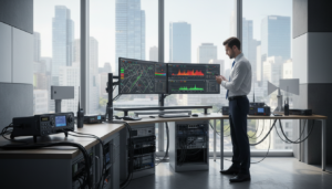
Quantifying downlink and uplink power in dBm guides every design and installation choice we make. We begin with an RF survey that records measured signal strength in dBm across the site. Those readings show where coverage fails and whether a build solution is required.
RF survey and signal strength testing in dBm to determine need
We collect uplink and downlink readings with calibrated meters. Results are plotted and compared to standards to produce a clear pass/fail outcome for the building.
Construction-phase planning: site surveys and propagation modeling heat maps
Using field data and software, we create heat maps that predict coverage during construction. This reduces rework and keeps the project on schedule.
Antenna layout strategy for consistent radio coverage throughout the building
We place antennas to serve stairwells, basements, and elevator lobbies. The goal is predictable, floor-to-floor coverage rather than spot fixes after occupancy.
System installation with code-aligned documentation and labeling
Installation follows conduit protection, secure mounts, and clear labeling. We deliver as-built drawings, equipment lists, and tag schedules to support inspection and owner records.
Acceptance testing and turnover for AHJ review
- Final testing verifies dBm targets and radio coverage per requirements.
- We package test logs, heat maps, and commissioning reports for AHJ review.
- Turnover includes operational manuals and maintenance contacts for the owner.
Code compliance, UL 2524 certification, and authority requirements in the United States
Regulatory frameworks establish when in‑building coverage is required and how it must perform. We follow model codes and listed standards so owners meet permitting, inspection, and life safety expectations.
How codes drive requirements
IBC and IFC set the trigger points for coverage requirements. NFPA codes then specify performance, testing, and documentation that owners must provide for acceptance.
What UL 2524 certification means for owners
UL 2524 evaluates products for fire and shock safety, reliability, and documented performance aligned to IFC and NFPA guidance. Certified equipment reduces AHJ questions and speeds approval.
| Covered component | Why it matters | Typical deliverable |
|---|---|---|
| Signal boosters and repeaters | Assures safe operation under load | Manufacturer listing and test report |
| Power supplies & battery charging | Supports life safety uptime | Runtime documentation and wiring diagrams |
| Remote annunciators & consoles | Interface for monitoring and alarm | FA wiring and commissioning logs |
AHJ scope and agency support
The local authority having jurisdiction decides which responder groups must be included. Typical groups are fire, fire mutual aid, police, and EMS.
Planning tip: obtain AHJ direction early and document which agencies require access and testing.
FCC consent under 47 CFR Part 90.219
Federal rules require express consent from the frequency licensee before amplification is installed. We verify licensee approval to avoid non‑compliance and project delays.
Ongoing inspection, testing, and maintenance to keep your system dependable
Proactive maintenance protects performance when construction or new devices alter indoor signal paths. We follow jurisdictional calendars so owners remain in good standing and occupants stay safe.
Jurisdiction-driven inspection schedules and performance verification
Inspection cadence and verification
Many local agencies require periodic inspections and testing. We track AHJ dates and deliver documentation to support compliance.
Performance verification means re-checking coverage and signal strength after changes such as tenant fit‑outs or new RF sources. We retest areas that show degradation and log results for future audits.
Preventive maintenance for BDAs, power supplies, batteries, and annunciation
Routine tasks include BDA checks, power supply diagnostics, battery load tests, and annunciator validation. These actions prevent silent failures caused by aging components.
We supply scheduled tune‑ups and parts lifecycle plans so the full chain remains dependable for responders and fire personnel.
Service response to protect signal strength and reliability
When alarms or faults appear, we troubleshoot quickly, restore affected areas, and document corrective work. We coordinate with building staff to limit disruption.
“Timely maintenance turns unknown risk into predictable performance.”
Result: verified coverage gives responders reliable communications during critical events and reduces operational uncertainty for fire teams.
Conclusion
When a building shows poor public safety radio coverage, an ERCES is often the most practical path to restore reliable in‑building links for responders.
We recommend a clear decision flow: confirm weak signal with an RF survey, then move to engineered design, installation, acceptance testing, and scheduled maintenance. A properly executed ERCES supports life safety and helps owners meet jurisdictional compliance and standards.
Expect these building blocks in your scope: BDA, DAS, interior antennas, and resilient power plus monitoring. For assessment or project planning, contact Marconi Technologies at 55 Broadway 3rd floor, New York, NY 10006, or call (212) 376-4548 to schedule a site review.